Mechanical considerations
The mechanical structure of the robot plays a major role in this experiment. The most important mechanical design guideline that we have followed is:
Create a stable structure that allows the robot to react faster to changes in the environment.In order to achieve the objectives of stability and fast reaction, we have considered symmetry, weight, wheels and sensor position. These factors are explained in the following sections.
 |
Robot symmetry and weight distribution
The robot symmetry is a key factor in this case. Since the robot is going to self maintain balanced just with two contact points with the surface, it should be constructed in a way in which the center of mass is in the center of the structure. Optimally, the lower the center of mass in this vertical line, the better. An ideal solution would be to analyze the weight of all the lego bricks involved in the construction and its distribution, in order to construct an optimized structure. However this can easily take a considerable amount of time, so we have decide to take as a base the structure proposed in [3].
Wheel position and type of wheels
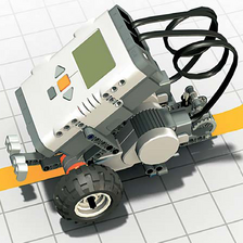
The lego robot proposed in [3] can be seen in the figure above. It is using the wide curved wheels that appear on the left in the next picture. The wheel selection is highly important, since they are the contact point with the surface. As general considerations, it is worth to remark that:
- The wider the wheels the better, since the contact surface with the floor is greater.
- The greater the radius of the wheel the better. This has further implications and it is connected with the motor performance. Consider a wheel with radius r1 and a second wheel with radius r2 so r1 <>
- The greater distance between the wheels, the better. If the separation between the wheels is bigger, this will help distributing the weigh of the robot and it will gives more stability. With an optimized weight distribution this will not have that much repercussion, but in our case, it introduces an important improvement.
Taking in account previous factors we decide to try with different wheel types available at the lab (see following picture). An ideal wheel should have the width of the wheel type that appears on the center and the radius of the wheels on the right. Finally, we choose to construct our robot with the big wheels, since they were making the robot to react faster. This turned out to be a very important decision.
 |
Sensor position
The light sensor is used to determine the distance to the surface. It is important to consider where the sensor is going to be positioned in order to improve robot performance. Before doing that, the basic mechanical movement of the robot should be analyzed.
The movement could be resumed with the following diagram. The optimal position gamma is in normal position (90º). Two angular limits (alpha and alpha prima) express the maximum inclination from which the robot is going to be able to restore the 90º position, thus to balance. If the inclination exceed those limits, the robot will fall. With an even distribution of weight and a constant environment, both limits should be the same. In our case we will assume they are.
The movement could be resumed with the following diagram. The optimal position gamma is in normal position (90º). Two angular limits (alpha and alpha prima) express the maximum inclination from which the robot is going to be able to restore the 90º position, thus to balance. If the inclination exceed those limits, the robot will fall. With an even distribution of weight and a constant environment, both limits should be the same. In our case we will assume they are.
 |
Now, the question is ¿how can the sensor be positioned so a change in the inclination is detected as early as possible? ¿how can we get the best out of the sensor resolution? The answer is positioning the sensor as far as possible from the vertical central line of the robot. By doing so, the sensor will be getting close or far from the floor before the inclination of main robot body is beyond the recovery angles. Due to this reason we have modified the robot structure in order to position the sensor properly. We constructed in a way in which is possible to change the sensor distance to compare the robot performance in different cases. This arrangement can be seen in the following picture.
 |
Final robot structure
Taking in account the previously exposed mechanical considerations, we have created the self-balancing robot. The final results can be seen in the following pictures:
 |
 |
 |
Hardware considerations
Fully charged batteriesIt is important to have fully charged batteries while operating the self-balancing robot. It is just under those conditions were the motors are able to deliver the appropriate power to move the robot fast enough.
Sensor types
We have identified three other kind of sensors that potentially can offer a better performance of the robot.
An high precision ultrasonic sensor could be used in order to measure the distance to the floor, rather than sensing the light reflection. This would allowed the robot to operate in any environment regardless the environmental light conditions. Of course, by using an ultrasonic sensor, other constraints are introduced: no other ultrasonic sources should be operating nearby (other robots, bats ...) otherwise they could cause erroneous readings.
The most reliable option would be to use mechanical sensors: gyroscopes or accelerometers. Both type of sensors will allow the robot to measure the inclination in a very precise way. Again, as in the ultrasonic case, other kind of constraints are introduced: if gyros or accelerometers are used, the robot should not be operated in an environment with a strong magnetic field.
The best sensing strategy would be to combine different kind of sensors in the same robot by applying the principles of redundancy and dual control.
Software considerations
As a starting point we have taken the PID based controller proposed in [insert reference]. This controller is using integers instead of floats. One of the first modifications we did was to change all the integer parameters to float data types, in order to have a more precise calculations.
Since we have altered the physical structure of the robot, the same PID values are not valid anymore, so we had to determine empirically the most appropriate values to control the robot.
The initial parameter were the following ones:
static final int KP = 28;
static final int KI = 4;
static final int KD = 33;
static final int SCALE = 18;
And a power value base of 55, used in the following expression:
int power = Math.abs(pid_val);
power = 55 + (power * 45) / 100;
The first change we introduced was to readjust the integral constant to a higher value. This was not a good approach. The integral term has got a direct implication in the angle that defined the recovery angle. If the integral term is higher, the recovery angle threshold is lower, so it is much harder to control the robot. We decided to keep this value constant after some trials. The second trial was to change the SCALE value, that determines to which extent the pid value is going to influence the power change to compensate the inclination.
float pid_val = (float)(KP * error + KI * int_error + KD * deriv_error) / SCALE;
So the scale value was redefined to 10, a value that we kept since the robot was balancing well, as it can be seen in the following video.
The last improvement we introduce was to change the power base figure. The power base is used to determine the required power depending on the PID value as follows:
int power = (int) Math.abs(pid_val);
power = 35 + (power * 45) / 100; // NORMALIZE POWER
By changing the power base, the robot movement is slower, so it is easier to balance. The results can be seen in the following video.
int power = (int) Math.abs(pid_val);
power = 35 + (power * 45) / 100; // NORMALIZE POWER
By changing the power base, the robot movement is slower, so it is easier to balance. The results can be seen in the following video.
Conclusions
After completing this lab sessions, we have realized that it is highly important to create a good robot structure, with the robot purpose in mind. Mechanical aspects of the robot shall be considered during this stage and, even though we are not Mechanical Engineers, the most outstanding considerations are direct application of geometry and common sense.
We found out that is very difficult to determine the appropriate parameters for the PID controller empirically, without applying a systematic method.
Finally, it is important to analyze the relationship between the PID values and the physical repercussion in the actuators. Just by considering this relationship it is possible to improve the robot behaviour.
References
1. Ole Caprani - Lego Lab 4 http://legolab.daimi.au.dk/DigitalControl.dir/NXT/Lesson4.dir/Lesson.html
2. Steve Hassenplug Legway http://www.teamhassenplug.org/robots/legway/
3. Philippe Hurbain NXTway http://www.philohome.com/nxtway/nxtway.htm
4. Brian Bagnall, Maximum Lego NXTBuilding Robots with Java Brains
5. Gyroscope from Hi-technic http://www.hitechnic.com/cgi-bin/commerce.cgi?preadd=action&key=NGY1044
6. Accelerometer from Hi-technic http://www.hitechnic.com/cgi-bin/commerce.cgi?preadd=action&key=NAC1040
7. Final Sejway solution http://code.google.com/p/josemariakim/downloads/detail?name=Sejway.java&can=2&q=#makechanges